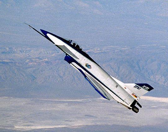
Alitson escreveu:F-20 Tigershark
Nesta sexta-feira tive de ir a Blumenau a trabalho e como de costume passei em uma banca de revistas usadas e lá achei uma revista Segurança e Defesa de 1987 que trazia uma matéria sobre o fim do projeto e nesta matéria está escrito que o projeto foi oferecido a Alemanha, Taiwan, Coréia do Sul e Brasil, dá pra acreditar???
Como a Northrop havia investido cerca de1,2 bilhões de dólares no projeto e para não perder tudo, ofereceu a estes paises o protótipo, documentos, ferramentas e o projeto completo, mas lá não constava qual o valor...
Para mim foi mais um erro dos nossos generais, o caça era superior ao F-16, F-4, F-5 e assim vai, pois este poderia ter colocado seu projeto em andamento com o AMX, estes poderiam compartilhar o motor, aviônicos, canhões, seria uma dupla perfeita, mas...

Textos tirados do site
http://members.aon.at/mwadeThe F-20 Tigershark was designed, built and tested by the Northrop Corporation in the early 1980's. Three prototypes were built, of which two crashed during sales demonstrations. The sole survivor was recently restored and now resides at the California Science Center in Los Angeles. The F-20 was the largest commercial military project ever attempted. Designed for the export market, Northrop invested $1.2 billion in the F-20 before it was cancelled by the company after six years of sales efforts. The lack of success in sales was due to shifting political sands in Washington, and unrelated to the aircraft itself, which was the first to fully exploit the digital electronics revolution and was the most advanced aircraft of its day.
• ENGINE AND FUEL
o F404 GE 100 18,000 Pound Thrust Turbofan Engine
o Pneumatic/Cartridge Starter or Optional Jet Fuel Starter
o 5,050 Pound Internal Fuel Capacity
o 330 Gallon Pylon Tank Capability--Three Stations
o Provisions for Air Refueling
o Halon Fuel lnerting System
• AVIONICS
o Digital Avionics with Built in Test (BIT)
o MIL STD 1553B Multiplexed Stores Management
o MIL STD 1750A Mission Computer
o Head Up Display (HUD)
o Hands on Stick and Throttle Controls
o ASN-144 Ring Laser Gyro Inertial Navigation Set
o AN/APG-67(V) Multimode Coherent Radar
o APX-101 Identification Friend or Foe (IFF)
o ARC-182 VHF/UHF Radio
o Radar Warning Receiver (RWR)
o ALE-40 Flush Mounted Countermeasures Dispenser System
o ARN-118 TACAN
• AIRFRAME
o 9G 8,000 Hour Airframe
o Dual Digital Flight Control System with 3 Axis Control Augmentation, plus Full Time Mechanical Backup System
o Autopilot
o Automatic High Rate Continuous Maneuvering Flap System
o Zero Altitude/Airspeed Ejection Seat
o Antiskid Carbon Brakes
o Onboard Oxygen Generating System (OBOGS)
o Graphite Composite Tail Skins
o Reduced Detectability, Increased Survivability
The F-20A avionics system incorporated the highly reliable General Electric AN/APG-67(V) radar, designed for a 200 hour MTBF. It was an X - band, pulse - doppler, digital, multimode radar, using low pulse repetition frequency (PRF) in the look up mode, medium PRF in the look down mode, and high PRF for velocity search.
The detection range of the AN/APG-67(V) permitted the F-20A to detect most adversary aircraft before the F-20A, with its low radar cross section, was detected by the adversary.
Radar
• Modular design
• X band coherent pulse doppler
• Digital, multimode
• Low, medium. and high PRF
• FUNCTIONS
o AIR TO AIR
Look up, look down range while search
Velocity search
Single target track
Air combat modes with automatic acquisition
Track while scan*
o AIR TO SURFACE
Ground map/doppler beam sharpened map
Display freeze mode
Ranging
Moving target indication*
Moving target track*
Beacon track (option)*
o AIR TO SEA
Sea surface search (SEA 1)
Sea moving target indication (SEA 2)*
Sea moving target track*
• CAPABILITIES
o Range: 80 nmi (maximum displayed)
o Angular coverage: 160 degree cone
o Map resolution: 45 feet at 5.0 nmi
o Beamwidth: 3.7 degrees azimuth, 5.4 degrees elevation
o Air to ground range accuracy: 50 feet or 0.5 percent of range
o Air target detection (fighter size target) --Look up--47 nmi --Look down--38 nmi
o Sea target detection (patrol boat size target) --Sea 1--47 nmi --Sea 2--40 nmi
• CHARACTERISTICS
o Antenna: 16.7 by 26.2 inches
o Power: 2340 VA
o Weight: 270 pounds
o Volume: 3.1 cubic feet
o Reliability: 200 hours MTBF

The F-20A integrated avionics system provided air to air and air to ground target detection and weapons delivery for supersonic intercept, air superiority, combat air patrol, close air support, and interdiction missions----day or night and under adverse weather conditions.
The avionics design simplified pilot operations, reduced pilot workload, and rapidly provided data for successful combat missions. The design incorporated the newest USAF avionics standards. Primary avionics elements were integrated through a redundant MIL STD 1553B multiplex data bus and controlled by a MIL STD 1750A mission computer using MILSTD 1589 Jovial J 73 language. The computer contained 256,000 words of programmable memory and had a throughput of 1 million operations per second. The computer had a specified MTBF of 2400 hours. The F-20A was able to accept new MIL STD avionics and weapons with a minimum of modification and without additional wiring to the avionics.
TIGERSHARK CONTROLS AND DISPLAYS
The Tigershark display system consisted of two digital display indicators (DDIs), a head up display (HUD), a data entry panel, and a display processor. Integrated controls included a data entry panel, software controlled push buttons surrounding each DDI, and hands on stick and throttle (HOSAT) switches.
The two DDIs, located in the uppermost part of the main instrument panel, were easily visible to the pilot. The left DDI usually displayed mission data; the right DDI was normally assigned to the radar.
When a combat mode was selected by the stick or throttle switches, the HUD and DDIs changed immediately to the appropriate displays; the right DDI displayed the radar format while the left DDI displayed stores management data. The figure below illustrates a typical air to ground stores display with bombs selected.
HEAD UP DISPLAY
The HUD provided head up capability in all modes of flight: weapons aiming and delivery information for air and ground targets, and navigational and flight data. The HUD presented data and sufficient references (aim point, allowable steering error, launch boundaries, attitude, and weapon selection and status) to enable navigation and target acquisition and designation. Air to ground weapons could be released manually using the stick switch or automatically by the mission computer. The figure below shows a typical HUD display for an air to air engagement using AIM 9 missiles.
TIGERSHARK RADAR
The Tigershark avionics system included the General Electric AN/APG-67(V) radar. This radar was an X -band, pulse doppler, digital multimode radar using low pulse repetition frequency (PRF) in the look up mode, medium PRF in the look down mode, and high PRF for velocity search. It had an MTBF of 200 hours and included the following functions:
• AIR TO AIR --Look up, look down, range while search --Velocity search --Single target track --Air combat modes with automatic acquisition --Track while scan*
• AIR TO SURFACE --Ground map/Doppler beam sharpened map --Display freeze mode --Ranging --Moving target indication* --Moving target track* --Beacon track (option)*
• AIR TO SEA --Sea surface search (SEA 1) --Sea moving target indication (SEA 2)* --Sea moving target track*
INERTIAL NAVIGATION SET (INS)
The F-20A AN/ASN-144 ring laser gyro INS was the primary navigation, attitude, and heading reference. It provided an all attitude self contained navigation capability anywhere in the world. Precision data were continuously available without degradation during all types of maneuvering and speed ranges. INS accuracy was better than 1.0 nmi/hour CEP.
The ring laser gyro used no moving parts. It operated by measuring the frequency difference between two counter rotating laser beams. The simplicity of the ring laser gyro resulted in a specified MTBF of 2000 hours and significantly improved navigation performance and rapid alignment.
The INS alignment time was 22 seconds, using position data stored prior to aircraft shutdown to facilitate fast scramble time.
BUILT-IN MAINTENANCE DIAGNOSTICS
The Tigershark featured built in (on board) system maintenance diagnostics for detection of failures at the line replaceable unit (LRU) level. Thus, no avionics flight line support equipment was required and scheduled inspections were reduced. Built in test (BIT) capability was included in the LRUs of the avionics system and the electronic flight control system. BIT failure data was processed by the mission computer and displayed on the digital display indicator.
When BIT indications resulted in LRU removal and replacement, the failed LRU was repaired at the intermediate level shop LRU test station using already available test equipment and off the shelf computers. Intermediate level testing identified the fault to the shop replaceable unit (SRU), which was then replaced; the failed card was then forwarded to the depot or supplier for repair.

Flight Controls
Dual Digital Flight Control System With 3 Axis Control Augmentation Plus Full Time Mechanical System
The F-20A used advanced aerodynamic technology to achieve high performance with an unrestricted flight envelope. Leading edge extensions (LEX) were carefully designed to control forebody vortices and to provide increased vortex induced lift. The maneuvering flap system provided continuous automatic flap operation to enhance wing efficiency. In the automatic mode, flaps were automatically positioned at the optimal setting as a function of airspeed, angle of attack, pitch rate, normal acceleration, and stick position. Excellent stability characteristics throughout the flight envelope eliminated the need for control system limiters, which otherwise would preclude attainment of maximum angle of attack or limit load factor.
The flight control system combined the advantages of an electronic, or fly by wire, system with the safety and reliability of a mechanical system. Primary flight controls included an all movable horizontal stabilizer, ailerons, and rudder. The flight controls in all three axes were controlled through a combination of pilot-commanded mechanical inputs and the dual digital three axis Control Augmentation System (CAS) commanded by the Flight Control Electronics Set (FCES). In the pitch axis, for example, the CAS system accounted for approximately 40 percent and the pilot's mechanical input for approximately 60 percent of the total control authority of the horizontal stabilizer.
Should the highly reliable FCES have failed for any reason, the mechanical system had sufficient authority under all loading conditions to control and land the aircraft safely.
The F-20A flight control system produced the following benefits:
• Low pilot workload
• Low maneuvering control stick forces
• Neutral speed stability during gear up acceleration
• Reduced control stick movement
• Uniform aircraft response
• Improved tracking capability
• Operational enhancement
• Allowed neutral stability center of gravity position
• Eliminated ballast requirements.
AUTOPILOT
The F-20A autopilot provided the following HOLD modes:
• Attitude
• Heading
• Altitude
• Mach/airspeed
A control stick steering mode automatically disengaged the selected HOLD mode when the stick was moved and reengaged when the selected conditions were met and the stick was released.
HANDLING QUALITIES
Excellent handling qualities were provided throughout the flight envelope by a combination of aerodynamic characteristics and a flight control system optimized to allow precise control with reduced pilot workload. Above 350 KCAS, a constant maneuvering stick force gradient of approximately 4 pounds per g was provided. Below 350 KCAS, where the aircraft could maneuver to maximum lift conditions at high angles of attack, the gradient increased with decreasing airspeed to yield a constant stick force as a function of pitch rate. The F-20A's high degree of departure and spin resistance and its highly responsive flight system allowed the pilot to maneuver aggressively without fear of departing the aircraft.
Performance and operational reliability of the flight control electronics system (FCES) were achieved by a dual digital flight control computer (FCC). The FCES combined high reliability with a simple actuation scheme that capitalized on performance gains of relaxed static stability while achieving excellent handling qualities. In the event of multiple failures of the FCES, control reverted to the active mechanical control system, with handling qualities sufficient to allow the pilot to return to base and land safely.
Increased mission operational reliability was provided in the FCES through dual channels of air data computation by the digital air data unit (DADU). The DADU supplied Mach number, altitude, and dynamic pressure data to the FCC and the mission computer.
Required air data parameters were computed and transmitted by the DADU to the radar, HUD, and environmental control system through the FCC interface with the MUX bus.
OVERSTRESS REMINDER
The F-20A flight control system incorporated a computer controlled "g reminder" system designed to prevent inadvertent overstress of the aircraft. As the aircraft reached limit load factor, the normally low and constant stick force per g increased substantially, informing the pilot that he was at design limit load factor. Limit load factor was automatically computed by the pitch CAS computer as a function of external stores loading and fuel state. In an emergency situation, however, the pilot could override the system by pulling through the increased resistance.
Reliability and Maintenance
RELIABILITY SUMMARY
The F 20A Tigershark demonstrated unprecedented reliability throughout the flight test program.
Mission reliability during the flight test program was consistently greater than 95 percent. Field measured data indicated that the F-20A reliability was 159 percent better than anticipated. These data confirmed Northrop's approach to reliability and showed that the expected level at maturity of 6.00 field inherent MFHBF (mean flight hours between failure) was conservative.
MFHBF
Avionics 18.07 MFHBF
Engine 190.00 MFHBF
Airframe 9.43 MFHBF
-------------
Total aircraft 6.00 MFHBF
MAINTAINABILITY SUMMARY
Design assessments, demonstrations, and measured data indicated that the specified 5.6 direct maintenance man hours per flying hour (DMMH/FH) maintainability requirements for scheduled and unscheduled organizational and intermediate levels of maintenance would be met before 100,000 cumulative fleet flight hours. Three quarters of the F-20A maintainability figures were based on measured empirical data.
Field measurements were conducted on flight test aircraft at Edwards Air Force Base, California. Intermediate and depot level support were provided by Northrop suppliers; therefore, these data were not measured. However, all organizational level maintenance data were collected.
MAINTENANCE INDEX (Maintenance Man Hours per Flight Hour)
Airframe & systems 2.64
F404 GE 100 engine 0.45
Avionics 0.52
----------
Total unscheduled maintenance - intermediate level 3.60
Inspection 2.00
----------
Total (DMMH/FH) 5.60
General support 5.50
----------
Total (MMH/FH)--organizational and intermediate levels 11.10